14.Arduino learning notebook-ITG3200/3205 gyroscope sensor experiment
14.Arduino learning notebook-ITG3200/3205 gyroscope sensor experiment
gyroscope
Juvtmall ( a company supply PCB Prototyping, PCBA service and sell kinds of components, modules and so on)
It is a device for sensing and maintaining direction, based on the theory of the immortal angular momentum. The gyroscope is mainly composed of a wheel which can be rotated around the axis. Once the gyroscope starts rotating, the gyroscope has a tendency to resist the direction of change due to the angular momentum of the wheel. The gyroscope is used for navigation, positioning and other systems. In 1850,in order to study the earth's rotation, French physicist J.Foucault discovered the rotor of the high-speed rotation. Because of its inertial effect, its axis of rotation always points in a fixed direction. He uses the Greek word gyro (rotation) and skopein (see), gather these two words into one word: gyro scopei , named this kind of instrument.
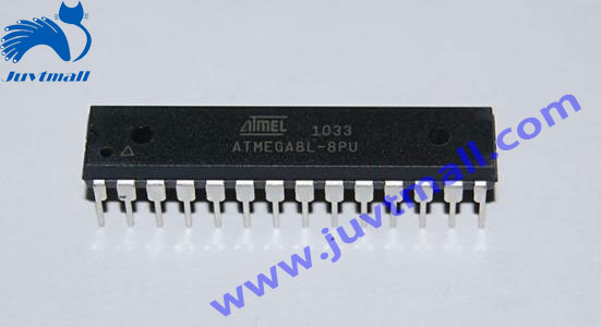
Let's look at the structure of the gyroscope


The chip used is ITG 3205, the way of use is consistent with ITG 3200. Through IIC interface connection, the measured result is angular velocity, unit is "degree/second".

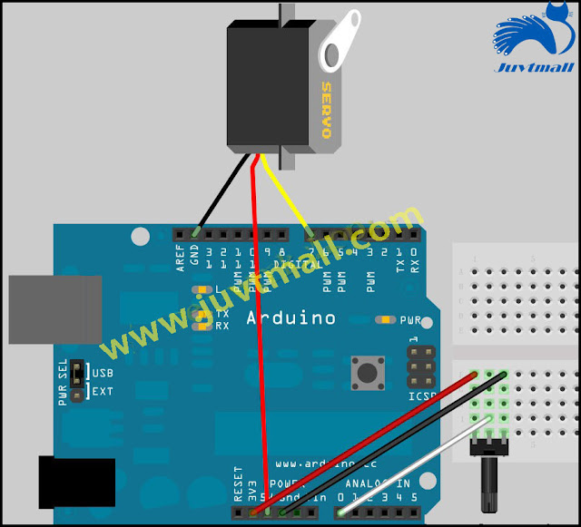
Here is the hardware connection diagram


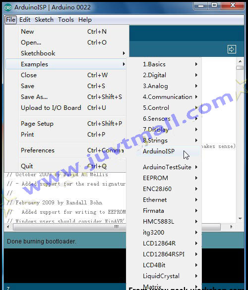
ARUINO CODE
1. #include <Wire. H > // call the I2C library brought by arduino
2. #include <LiquidCrystal. H > // call the LiquidCrystal library of arduino
3.
4. // define the ITG3200 gyroscope as constant
5. #define GYRO 0x68 // set IIC address, AD0 is connected with GND, and the binary value is 11101000.
6. # define G_SMPLRT_DIV 0 x15
7. # define G_DLPF_FS 0 x16
8. # define G_INT_CFG 0 x17
9. # define G_PWR_MGM 0 x3e
10.
11. #define G_TO_READ 8 // x, y, z output is 2 bytes per axis
12.
13. LiquidCrystal LCD (12, 11, 10, 9, 8, 7);// set the LCD interface
14.
15. // XYZ triaxial offset correction
16. Int g_offx = 28;// correct the X axis error
17. Int g_offy = 53;// correct the Y axis error
18. Int g_offz = 15;// correct the Z axis error
19. Int hx, hy, hz, turetemp;
20.
21. // initialize the gyroscope
22. void initGyro ()
23. {
24. / * * * * * * * * * * * * * * * * * * * * * * * * * * * * * * * * * * * * * * * * *
25. * ITG 3200
26. * power management settings:
27. * the clock is selected as the internal oscillator
28. * no reset, no sleep mode
29. * no standby mode
30. * sampling rate = 1KHz
31. * the parameter is + / -2000 / SEC
32. * low-pass filtering = 5Hz
33. there is no interrupt
34. * * * * * * * * * * * * * * * * * * * * * * * * * * * * * * * * * * * * * * * * * * /
35. writeTo (GYRO, G_PWR_MGM, 0 x00);
36. writeTo (GYRO, G_SMPLRT_DIV, 0 x07);// EB, 50, 80, 7F, DE, 23, 20, FF
37. writeTo (GYRO, G_DLPF_FS, 0 x1e);// +/ -2000 DGRS/SEC, 1KHz, 1E, 19
38. writeTo (GYRO, G_INT_CFG, 0 x00);
39. }
40.
41.
42. void getGyroscopeData (int * result)
43. {
44. / * * * * * * * * * * * * * * * * * * * * * * * * * * * * * * * * * * * * * *
45. Gyro ITG - 3200 I2C
46. registration:
47. temp MSB = 1B, temp LSB = 1C
48. X axis MSB = 1D, x axis LSB = 1E
49. Y axis MSB = 1F, y axis LSB = 20
50. Z axis MSB = 21, z axis LSB = 22
51. * * * * * * * * * * * * * * * * * * * * * * * * * * * * * * * * * * * * * /
52.
53. int regAddress = 0x1B;
54. int temp, x, y, z;
55. byte buff [G_TO_READ;
56.
57. readFrom (GYRO, regAddress, G_TO_READ, buff);// read data from ITG3200
58.
59. result [0 = (buff[2 << 8) + g_offx;
60. result [1 = (buff[4 << 8) + g_offy;
61. "result [2 = (buff[6 << 8).
62. result [3 = (buff[0 < 8) | buff[1; // temperature
63.
64. }
65.
66. void setup ()
67. {
68. lCD. The begin (16, 2);// initialize LCD
69. delay (100);
70. wire. The begin ();// initialize I2C
71. delay (100);
72. initGyro ();
73. }
74.
75. void loop ()
76. {
77. int gyro [4;
78. getGyroscopeData (gyro);
79. hx = gyro [0/14.375; // the output value is converted to angular velocity, unit is degree/ second
80. hy = gyro [1/14.375;
81. hz = gyro [2/14.375;
82. turetemp = 35+ ((double) (gyro[3 + 13200)) / 280; // the output value is converted to Celsius
83.
84. lCD. The clear ();/ / clear screen
85. lCD. Print (" X = ");// make the screen display text X=
86. lCD. Print (hx);
87. lCD. SetCursor (8, 0);
88. lCD. Print (" Y = ");
89. lCD. Print (hy);
90. lCD. SetCursor (0, 1);
91. lCD. Print (" Z = ");
92. lCD. Print (hz);
93. lCD. SetCursor (8, 1);
94. lCD. Print (F = "");
95. lCD. Print (turetemp);
96. lCD. The print (char) (223);
97. lCD. Print (" C ");
98. delay (100);// delay 0.1 second, refresh frequency to adjust
99. }
100.
101. / / -- -- -- -- -- -- -- -- -- -- -- -- -- -- -- - function
102. // write the value to the address register in the accumulator
103. void writeTo(int DEVICE, byte address, byte val) {
104. wire. BeginTransmission (DEVICE);// start transferring data to the accumulator
105. wire. Send (address);// send the register address
106. wire. Send (val);// send the values to be written
107. wire. EndTransmission ();// end transmission
108. }
109.
110.
111. // read buff array data from the address register of accumulator
112. void readFrom(int DEVICE, byte address, int num, byte buff[) {
113. wire. BeginTransmission (DEVICE);// start transferring data to the accumulator
114. wire. Send (address);// send the read address
115. wire. EndTransmission ();// end transmission
116.
117. wire. BeginTransmission (DEVICE);// start transferring data to the accumulator
118. wire. RequestFrom (DEVICE, num);6 bytes of data is requested from the accumulator
119.
120. int I = 0;
121. while (Wire. The available ())
122. {
123. buff [I = wire.receive (); // receive a byte
124. I++;
125. }
126. wire. EndTransmission ();// end transmission
127. }
评论
发表评论