7.Arduino learning notebook--PWM control the LED
7.Arduino learning notebook--PWM control the LED
Juvtmall ( a company supply PCB Prototyping, PCBA service and sell kinds of components, modules and so on)
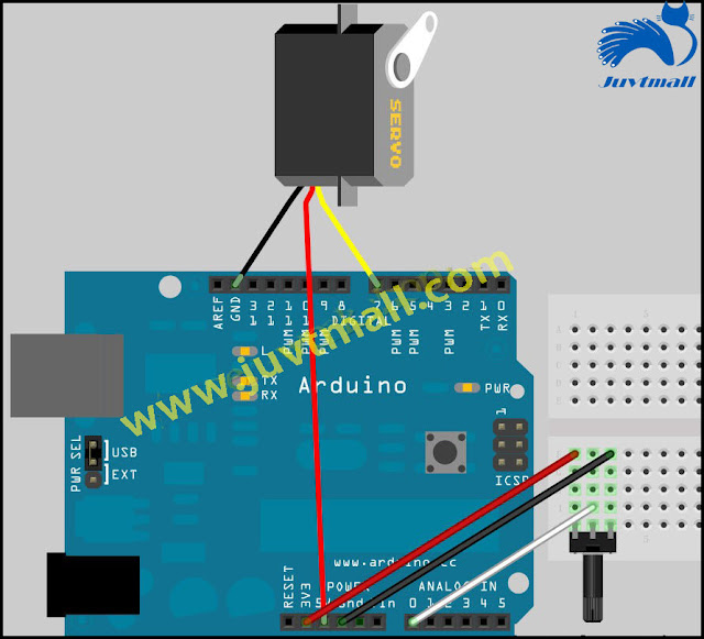
This experiment uses PWM to control a LED, which slowly turns bright and slowly darkens, then make a circle. Here is the wiring diagram:


ARDUINO code
1. / *
2.author: www.geek-workshop.com
3. components: control board, led, wire, bread board
4. usage: this experiment demonstrates how to make the light of LED connected to the port 9 gradually change through the analogWrite() command
5. * /
6. int brightness = 0;/ / define integer variables brightness and its initial value, this variable is used to represent the LED brightness.
7.int fadeAmount = 5;/ / define integer variable fadeAmount, which is used to reduce or add the amount of brightness change.
8.
9. void setup () {
10.
11. pinMode (9, the OUTPUT);/ / set port 9 as output port:
12. }
13.
14. void loop () {
15.
16. analogWrite (9, brightness);/ / write the value of brightness to 9 port
17.
18. brightness = + fadeAmount brightness;/ / change the brightness values, make the brightness change in the next cycle
19.
20. if (brightness = = 0 | | brightness = = 255) {
21. fadeAmount = - fadeAmount;/ / flip at the maximum brightness and minimum brightness
22. }
23.
24. delay (30);/ / delay 30 ms
25. }
Its function is to write a analog value (PWM wave) to the port.It can be used to control the brightness change of LED lights, or drive motors at different speeds.When the analogWrite () command is executed, the port outputs a stable square wave.Unless there is a next command to change it.The frequency of PWM signals is about 490Hz.
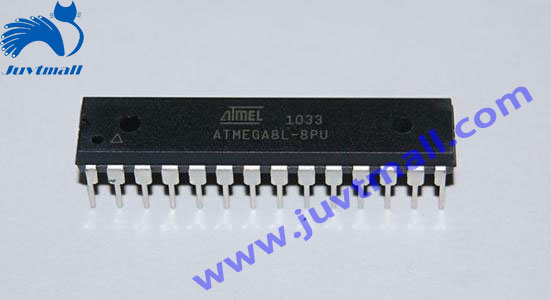
On the arduino control board with ATmega168 and ATmega328, the work is on port 3, 5, 6, 10, 11. Arduino Mega control board can work on port 2-13.On the older arduino control boardbased ATmega8, the analogWrite () command only works on port 9, 10, 11.Before using the analogWrite () command, you can define the port as the output port without using the pinMode () command, of course,it is better to define, which is convenient for the program language specification.
grammar
AnalogWrite (pin, value)
parameter
Pin: written port
Value: space ratio: between 0 and 255.
Notes and known problems
When PWM outputs and connect to the port 5, 6, it produces a higher duty ratio than expected.The reason is the internal clock used by the PWM output, and the millis () and delay () functions are also used. So when you use, you should pay attention to the port 5,6 and the duty ratio should be lower than the original set, or the port 5, 6 will not be able to output a completely closed signal.
PWM (Pulse - width modulation)
PWM is a method of using digital way to control analog output.The use of digital control produces a different square wave (a signal that switches between the open and the closed) to control the analog output.
In this experiment, the input voltage of the port is only two:0V and 5V.What if I want the output voltage of 3V?Some students said Series resistance, and this is the correct one.But what if I want to change back and forth between 1V, 3V, 3.5v and so on?It's impossible to switch the resistance all the time.In this case, the PWM should be used. For the arduino digital output, there are only LOW and HIGH voltage switches port, the corresponding is 0V and 5Vvoltage output. We define LOW as 0, HIGH is defined as 1.Let arduino output the signal of five hundreds 0 or 1 in one second. If all of these are 1, that's the complete 5V, if all of them are 0, that's going to be 0V. If the output is 010101010101, just one half is 5V, and the other half is 0V. That seems like to output the 2.5V voltage.This is the same as the film showing, the film we saw is not completely serial, it is actually output 25 images per second, but it is impossible to recognize it by our eyes. PWM is the same principle. If you want different voltage, control the output ratio of 0 and 1.There is a little difference with the actual continuous output, the more the 0, 1 signal output , the more accurate will be controlled.
In the figure below, every two neighbouring green lines represents a period, and its value is the inverse of the PWM frequency. In other words, if the frequency of arduino PWM is 500Hz, then the period between the two green lines is 2ms.The analogWrite () command can control the range of 0-255, The analogWrite (225) command represents 100% of the duty ratio (often opened), and the The analogWrite (127) command takes up approximately 50% (half of the time).

Traditional methods realize PWM
In addition to using the analogWrite () command to implement the PWM, you also can set through use traditional method to control the switch time of the level.
Arduino code
1. void setup ()
2. {
3.pinMode (13, the OUTPUT);/ / set port 13 as the output
4. }
5.
6. void loop ()
7. {
8. digitalWrite (13, HIGH);
9. delayMicroseconds (100);/ / about 1KHz square wave of 10 % duty ratio
10. digitalWrite (13, LOW);
11. delayMicroseconds (900);
12. }
The advantage of this method is that it can use any digital port as the output port.And you can arbitrarily set the duty ratio and frequency. But one major drawback is that any interruption will affect the clock, which will cause great shake unless you prohibit the interrupt.The second is that the CPU can't do anything else when it's processing the output.
The code above uses a new command
DelayMicroseconds ()
Its effect is to produce a delay, measured in microseconds, 1000 microseconds =1millisecond. At present delayMicroseconds () has a maximum value of 16383.If the value is greater than 1000, the delay () command is recommended.
评论
发表评论